Designing a 3D-Printed Motorcycle Top-Case Adapter in FreeCAD
I recently bought a top case for my motorcycle and ran into two problems: my bike's rear rack doesn't use a standard hole pattern, and the top case's mounting base was poorly made (it came from Temu, so that was no great surprise). Neither part fit the other, so I designed a 3D-printed adapter in FreeCAD that bolts between them. This is the full process, from taking measurements to the final assembly.
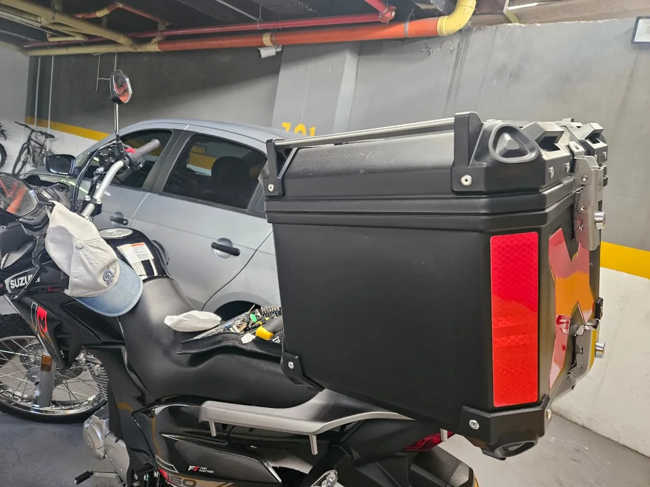
The weight budget
My bike's rear rack is rated for a 7 kg maximum load, according to the warning label stuck on it. The top case and its base weigh 4 kg, my helmet 1.2 kg, and what I usually carry inside — locks, reflective gear, tools — another 1.5 kg. That adds up to 6.7 kg, leaving the adapter at most 300 g. That number drove every design decision.
Measuring two parts that were never meant to fit
To design the adapter I needed the geometry of two parts: the motorcycle's rack and the top-case base. Specifically, the position of every hole and slot.
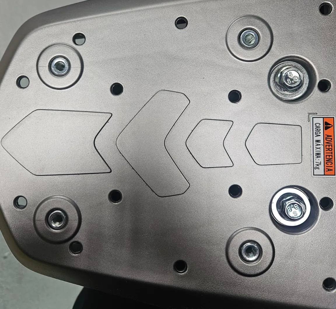
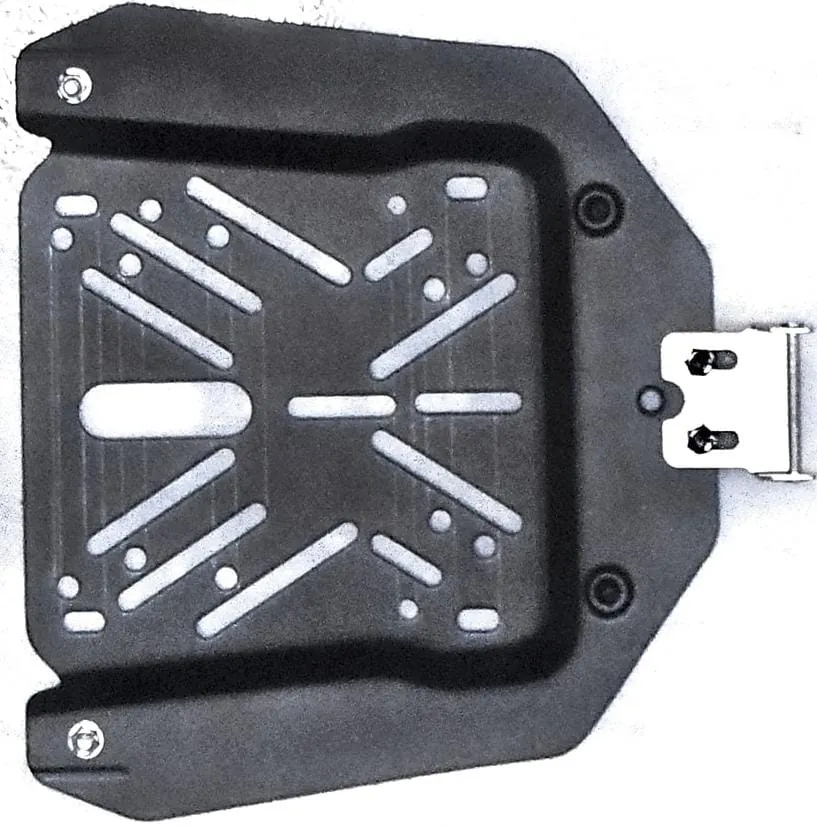
There are several ways to capture that geometry:
- Calipers and a sketch. Measure every hole and slot and transfer it to a sketch. Accurate, but slow, and with that many dimensions it's easy to make a mistake.
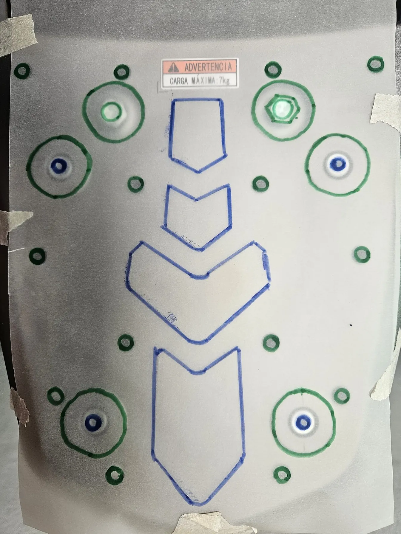
- Trace the part and scan the tracing. Works when the part is flat: trace the holes and outlines, scan the sheet, then calibrate the image in CAD.
- Take a photo. The fastest option, but perspective distorts the measurements depending on camera distance and angle, so it's no good for something that has to bolt together.
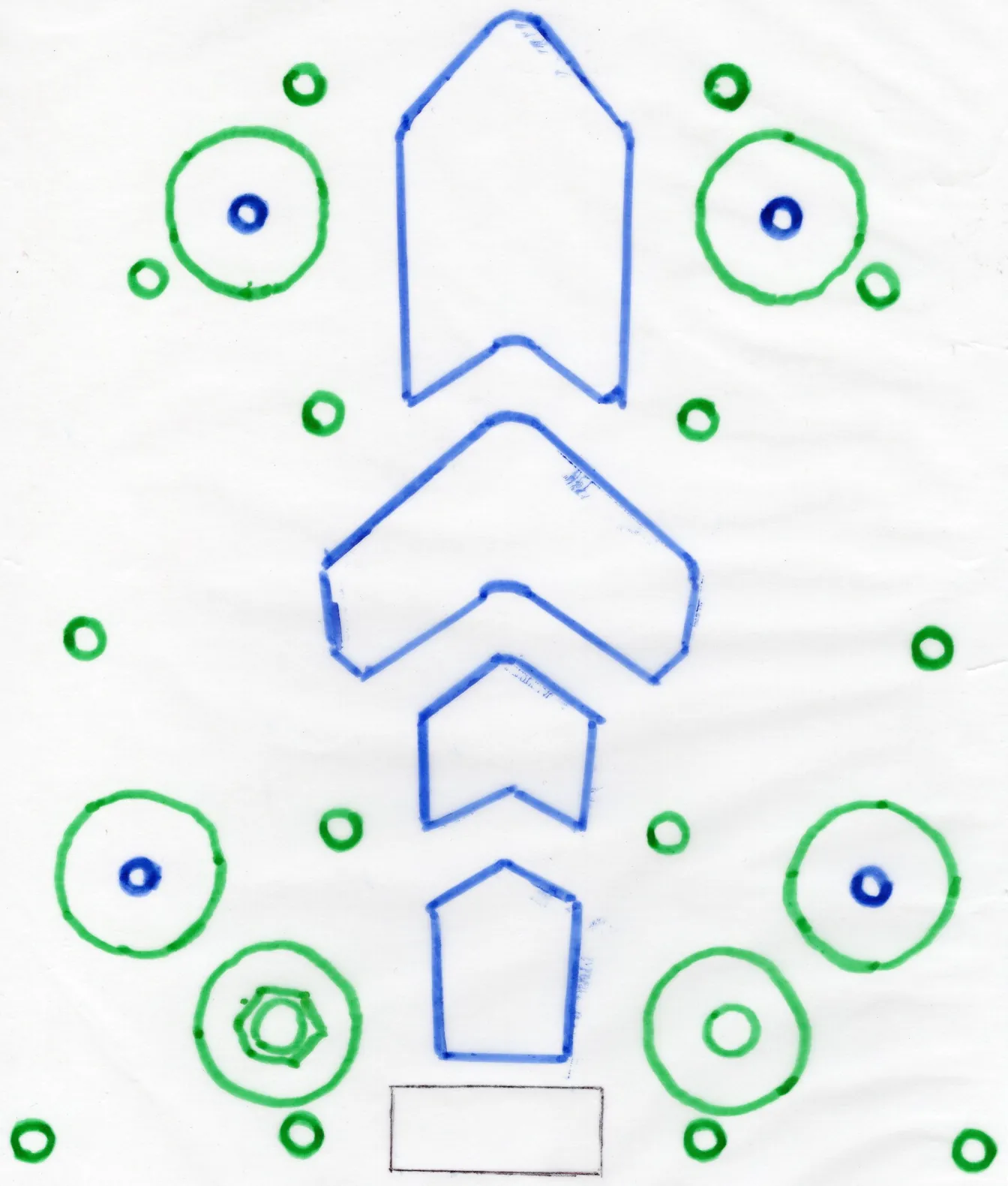
For the rack I went with tracing: I taped parchment paper over it, marked the holes and outlines with markers, and then scanned the sheet.
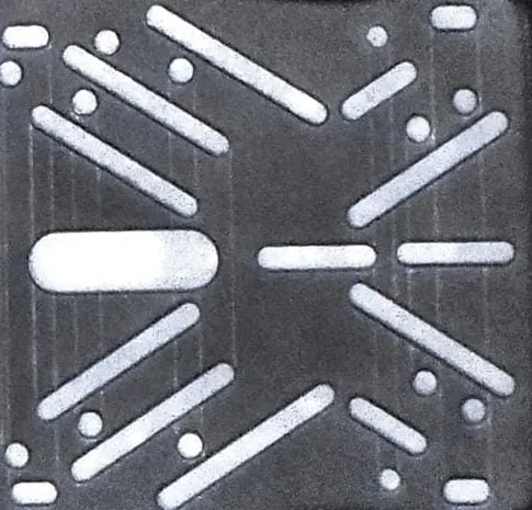
For the top-case base I took a more direct route. Since it has a flat face, I laid it straight on the glass of my printer's scanner. A flatbed scanner has no perspective problem, so the image comes out at true scale and undistorted — no tracing needed.
Calibrating the images in FreeCAD
I imported both scans into FreeCAD and used its scale-calibration tool: mark a known distance on the image, tell FreeCAD its real length, and it rescales the image. Both images then sit at true size, and you can sketch directly on top of them, tracing every hole and slot.
Aligning the two patterns
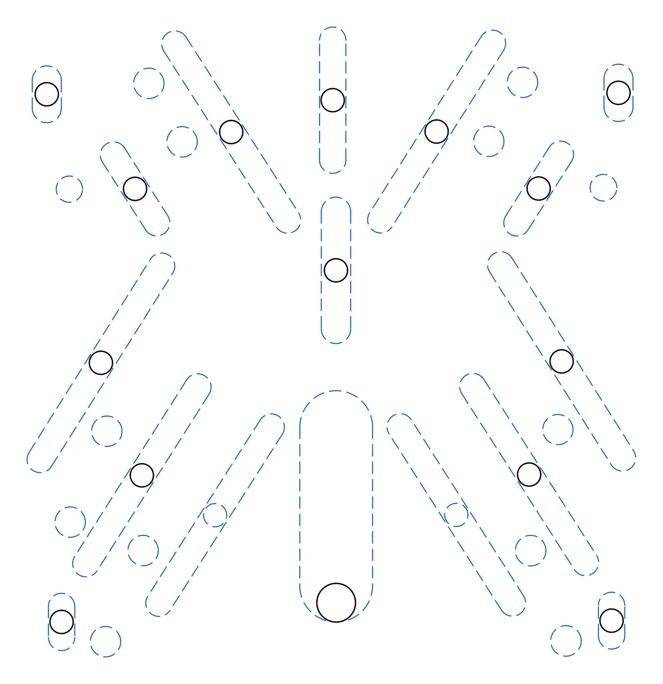
With one sketch per part, I kept one fixed and moved the other around on top of it. The goal was to get at least one or two of the rack's four M6 threaded holes lined up with slots in the base, so a bolt could pass straight through: top-case base, adapter, and rack.
After moving the sketch around a little, I found a position where two of the bike's threaded holes lined up with two slots in the top-case base, and left it there.
The base plate and its limits
The adapter starts as an extruded plate, and its footprint had three limits: the size of the rack, the size of the top-case base, and my printer's bed. Both the rack and the base are larger than the bed, so the printer set the limit: I started with a 19 × 19 cm square, big enough to cover everything needed and still inside the 21 × 21 cm print area.
Holes and captive nuts
I cut every bolt hole into the plate and then split them into two groups by function:
- Adapter → motorcycle. These bolts go into the rack's existing M6 threaded holes, so they need no nuts.
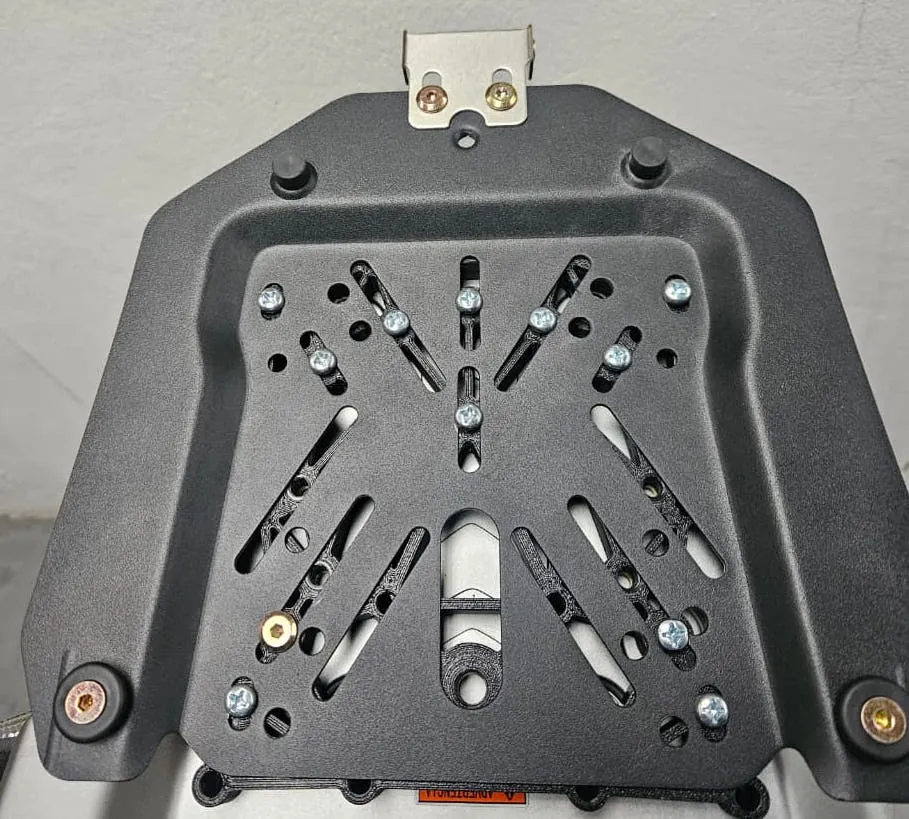
- Top-case base → adapter. These bolts pass through the top-case base and tighten into nuts captured in the adapter. For that I sketched each nut's size and cut hexagonal pockets that trap them. I only needed two sizes: M6 nuts and a single M10 nut.
Checking before printing
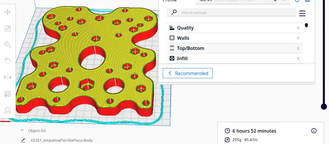
At this point I had a printable model, but I didn't print it yet. First I exported an STL and checked the print time and material in the slicer: 255 g and almost 7 hours. That fit within 300 g, but with very little margin, so I decided to remove material.
Removing material: from plate to truss
Back in FreeCAD, I created a new sketch from projected geometry. Around each bolt hole I drew a concentric circle and extruded it, leaving a base of separate cylinders that protect each hole. I then joined those cylinders with straight bars, forming a kind of lattice or truss: material stays where the bolts are, and the rest of the plate disappears.
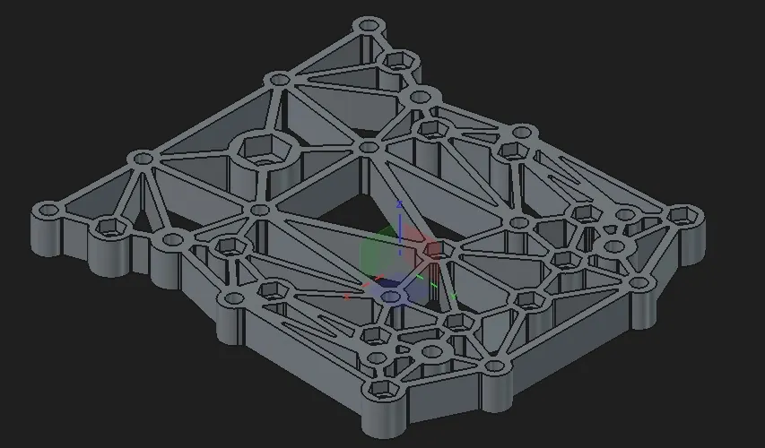
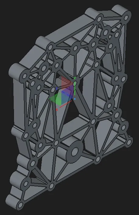
One detail: some bolts sit underneath the top-case base, and their heads need a recess so the base sits flat. Modeling that recess would have meant printing with supports that end up in the trash. It was faster to print the part completely flat and grind the recesses afterwards with a rotary tool.
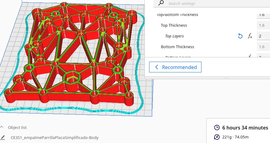
Re-slicing showed the difference clearly: the adapter dropped from 255 g to 221 g, filament from 85.47 m to 74.05 m, and print time from 6 h 52 min to 6 h 34 min.
Printing and assembly
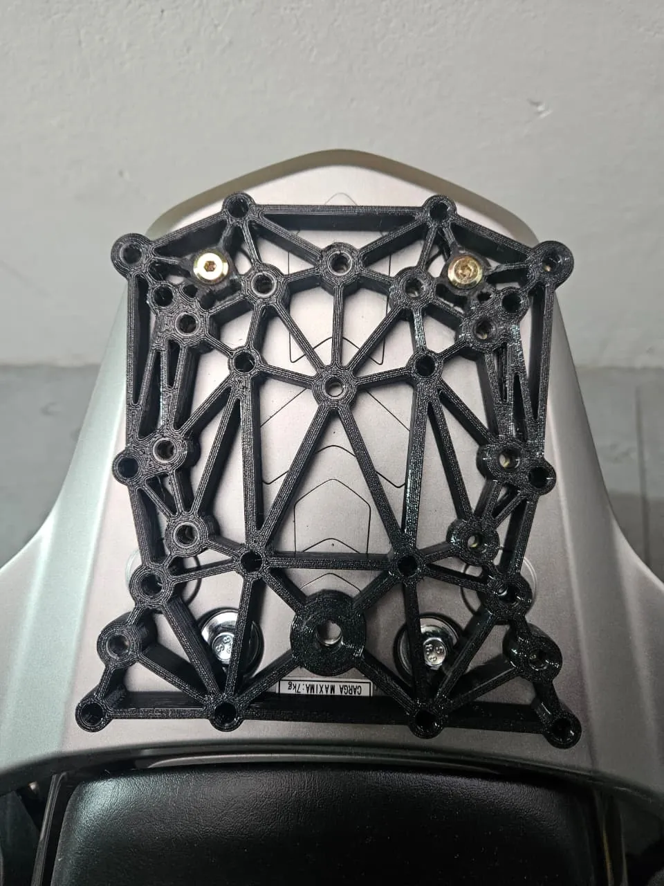
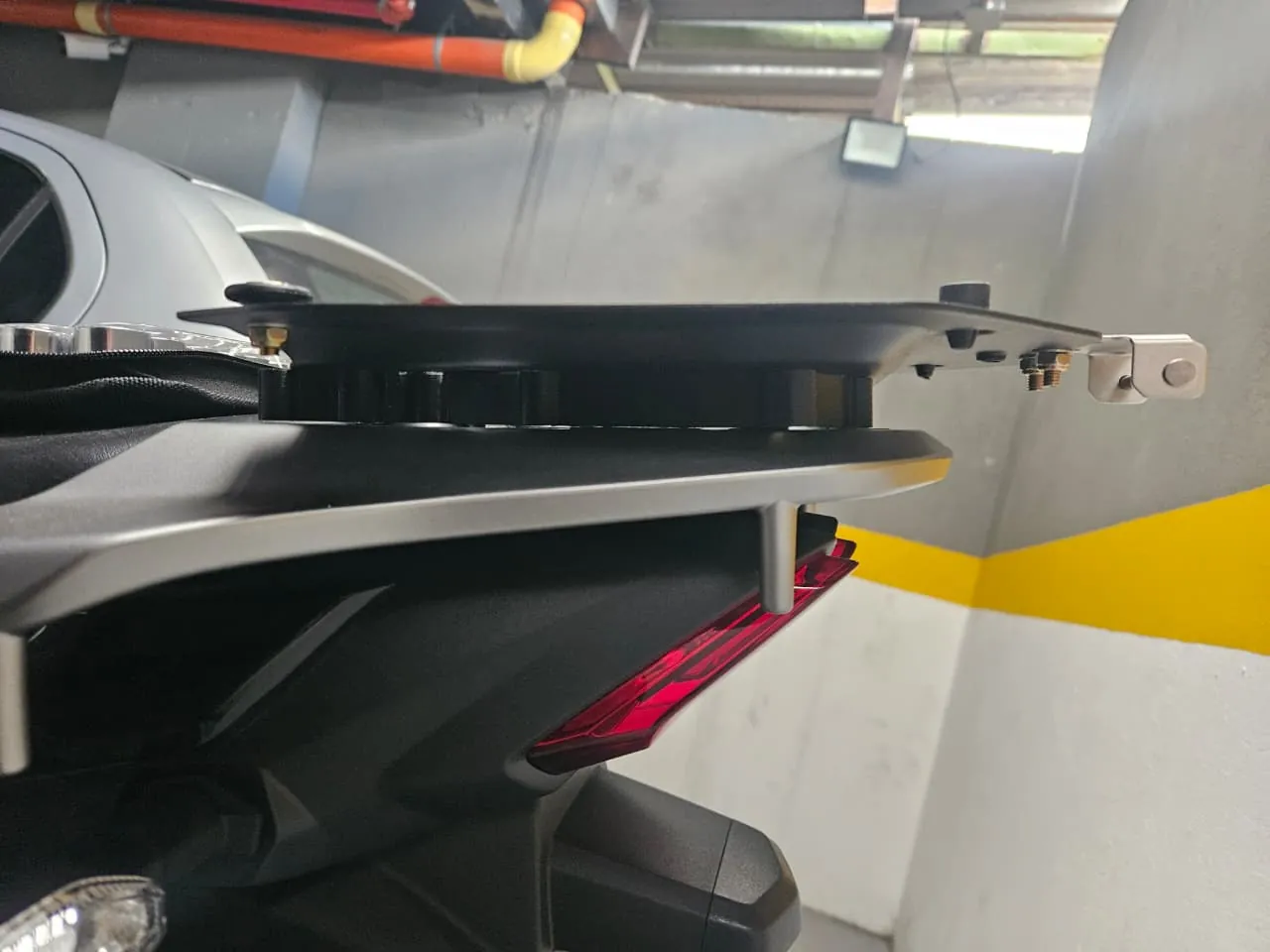
I printed the adapter in PETG, ground the recesses with the rotary tool, and assembled it: first the adapter onto the rack, then the top-case base onto the adapter. The finished part weighs about 220 g, 80 g under budget.
Bill of materials
- 221 g of PETG filament
- 11 × M6 × 40 mm round-head Phillips screws (top-case base → adapter)
- 11 × M6 nuts, captured in the adapter
- 4 × M6 flat-head hex-socket screws (adapter → motorcycle)
- 1 × M10 × 15 mm bolt
- 1 × M10 nut
Tools
- FreeCAD
- Creality Ender 3 V2 3D printer
- Rotary tool with sanding bit
- Flatbed scanner, parchment paper, and markers
CAD files
The adapter's CAD files are on GitHub: github.com/ElJoho/motoDR160X.
If I had to keep just one idea from this project, it would be the scanner: for flat parts, it gives true-scale measurements with no calipers and no perspective error.